Projects
Modernization of a classic super car.
Modernizing a classic super car like the first-generation NSX posed challenges due to aging components, particularly the ignition system. Original coil packs and external ignition modules, after enduring thousands of heat cycles, began to degrade in performance and reliability. The solution involved retrofitting modern coil packs from the Honda K series engines, which integrated an internal igniter chip, eliminating the need for the original ignition module. This adaptation not only improved reliability but also facilitated easier sourcing of parts from standard auto part stores.
The design process commenced with meticulous research to identify suitable coil packs with adequate power output and similar charging characteristics. The chosen K series coil packs were compact enough to fit within the NSX's engine bay and offered superior performance over the originals. Custom brackets and wiring harnesses were designed using 3D scanning and CAD software, ensuring precise placement and compatibility. Prototyping involved iterative 3D printing for brackets and careful material selection such as 6061 aluminum for heat resistance and durability, and DR25 for the wiring harness to withstand engine bay conditions. Manufacturing employed CNC machining and adhered to rigorous standards to ensure reliability and longevity.
After testing covering over 20,000 miles, the retrofit kit proved successful with no issues.

After discovering that there are some major size deviation between the two valve covers the best option was to 3d scan both covers and design the bracket in Fusion 360. The major challenge with this was ensuring that the coil packs and bracket were in the correct position, radially and axially with ensuring that these components can easily be installed.

The first several bracket prototypes were 3d printed, using FDM. this insured that the coil packs were in the correct location and it allowed for all the components to be easily assembled.
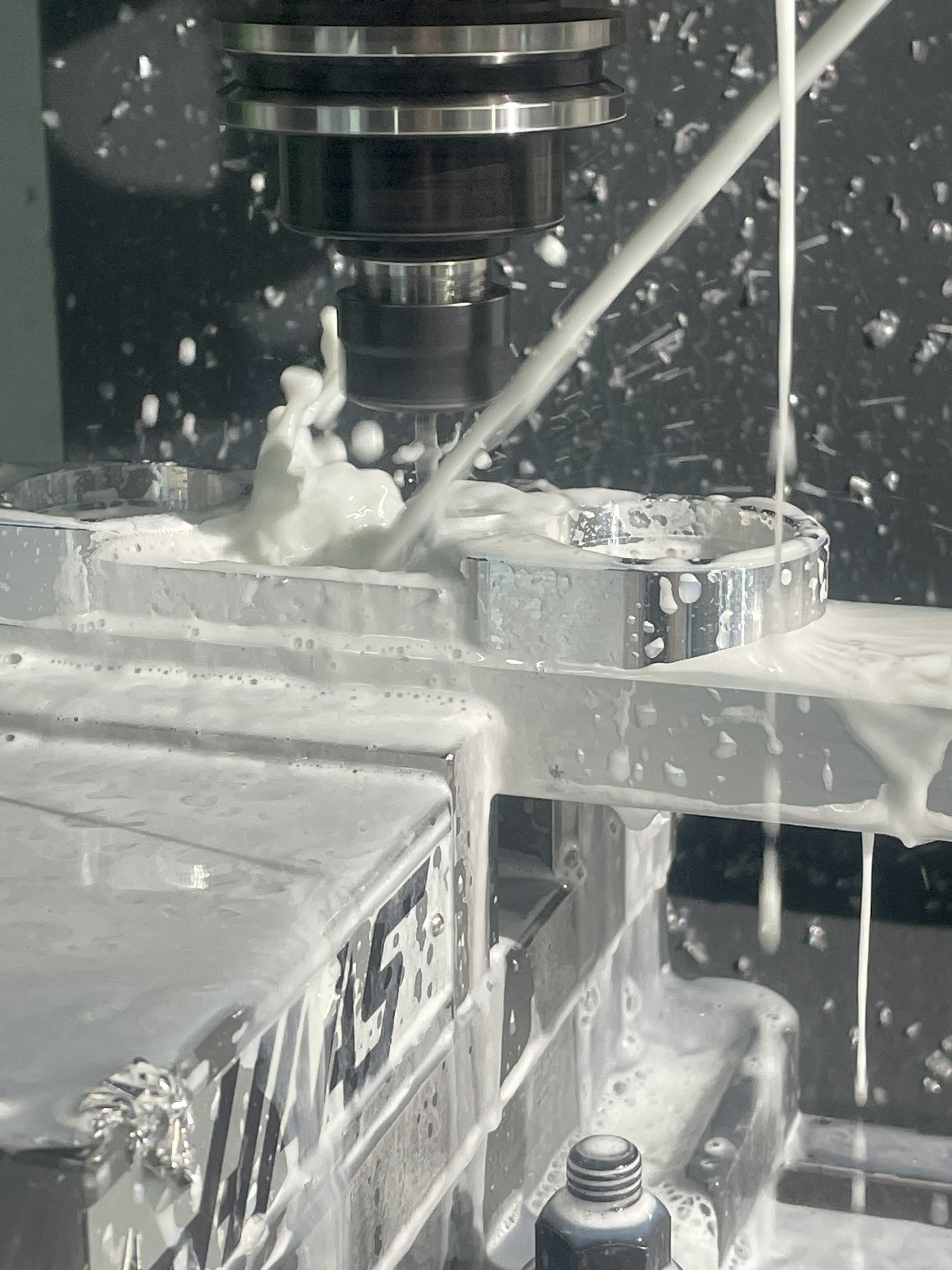
The machine that was used was a three axis so there would be a minimum of two operations. The origin was based off of cylinder one bore and the fixed jaw of the vice. This ensured that when the part was flipped over for operation two there would be dimensional accuracy between both operations.
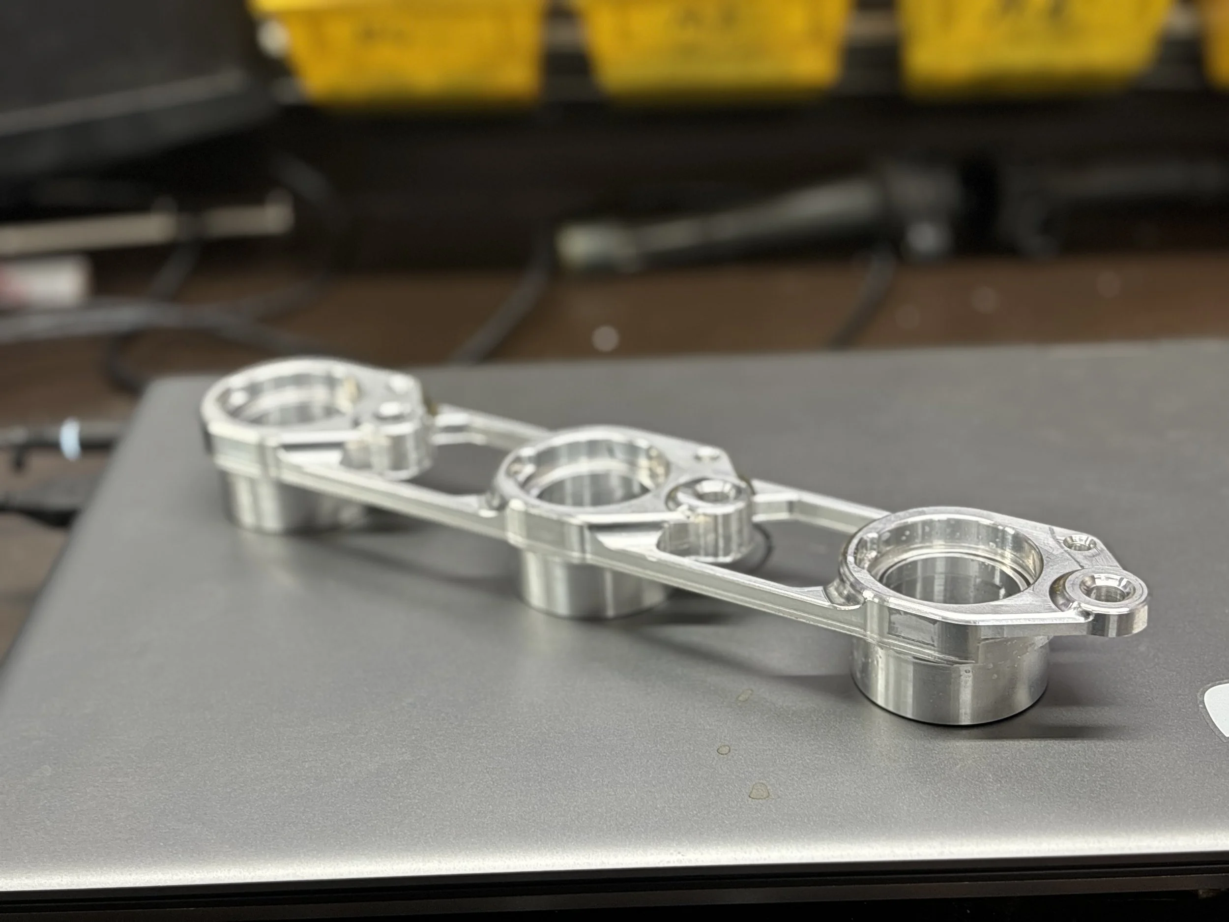
The first bracket completed.
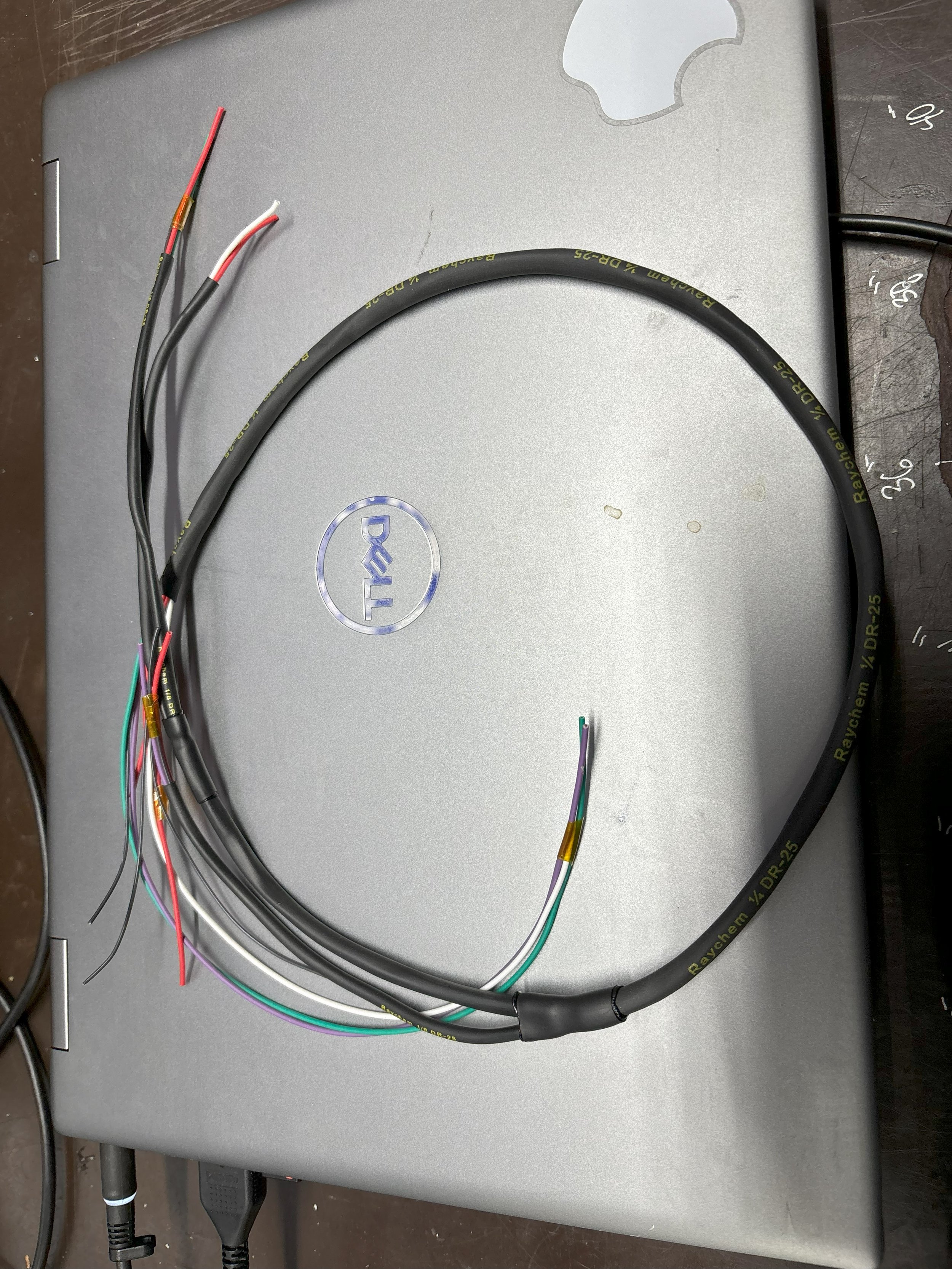
I used MIL-STD-681F as a guide for the harness, this ensured that the harness was manufactured to standards that would eliminated the chance of any improper crimp and the harness would survive in the harsh environment of an engine bay.

The bracket and wiring harness installed on bank two of the engine.

Both finished brackets and the completed wiring harness.
Reproducing parts using carbon fiber.
The problem of brittle OEM coil pack covers due to aging was addressed by developing a replacement using heat-resistant carbon reinforced plastic. The design process involved evaluating materials and selecting prepreg composites for their ability to withstand high temperatures. A new cover was conceptualized to match OEM aesthetics, using bidirectional twill material for strength. Prototyping revealed initial mold weaknesses, prompting a switch to an aluminum mold that improved durability and heat resistance. Manufacturing involved laying up two layers of fiber orientation and using a homemade autoclave for curing, resulting in parts with minimal flaws and no delamination.

The CAD model of the replacement coil pack cover. This was designed with draft angles to allow the part to be easily removed from the mold.

The initial design of the mold which include integrated vacuum ports and air ports to assist with de-molding.
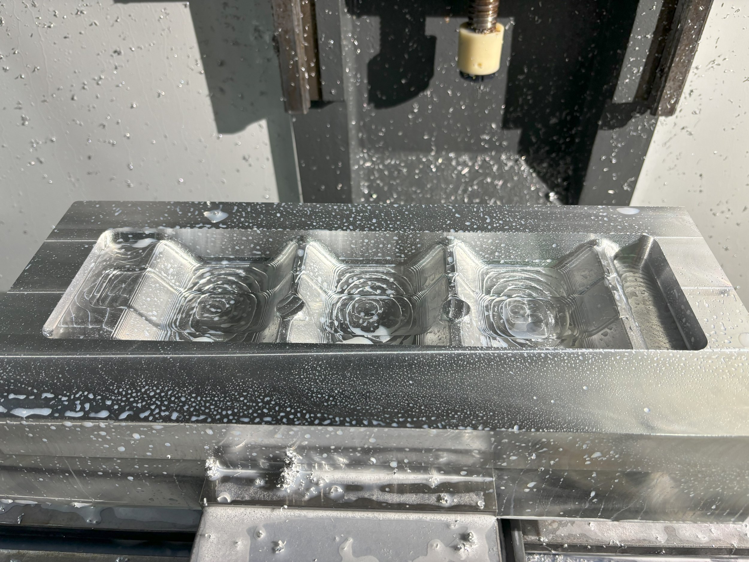
The mold after it was machined. This was completed in three operations due to the complexity of the vacuum and air ejection ports.

Using the 3d design I was able to create a flat pattern in Fusion 360 and the prepreg carbon was cut out. the material was laid into the mold in a +45, -45 fiber orientation which helped increase torsional ridigity. There was also reinforcement material added around bolt holes to increase strength.

The part removed from the mold after it went through the required temperature cycles in a custom made autoclave.

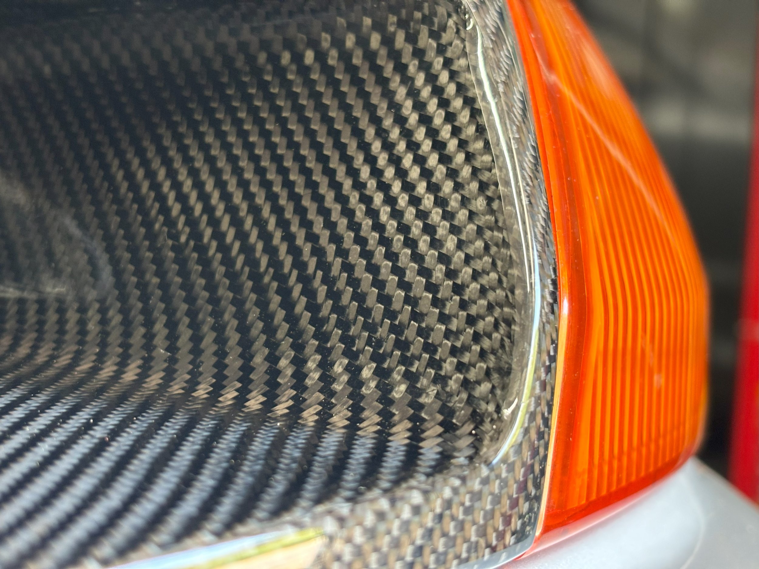
The finished product installed on the car.

Highlights from building a 1989 Nissan Skyline Gtr
Building a race car over six years is a journey that blends passion, dedication, engineering prowess, and teamwork. It's not just about assembling parts; it's about pushing boundaries, solving intricate problems, and perfecting every detail to achieve peak performance.

One of the byproducts of making over 1000hp is excessive crank case pressure. I designed a custom air oil separator and modeled the air velocity in CFD.
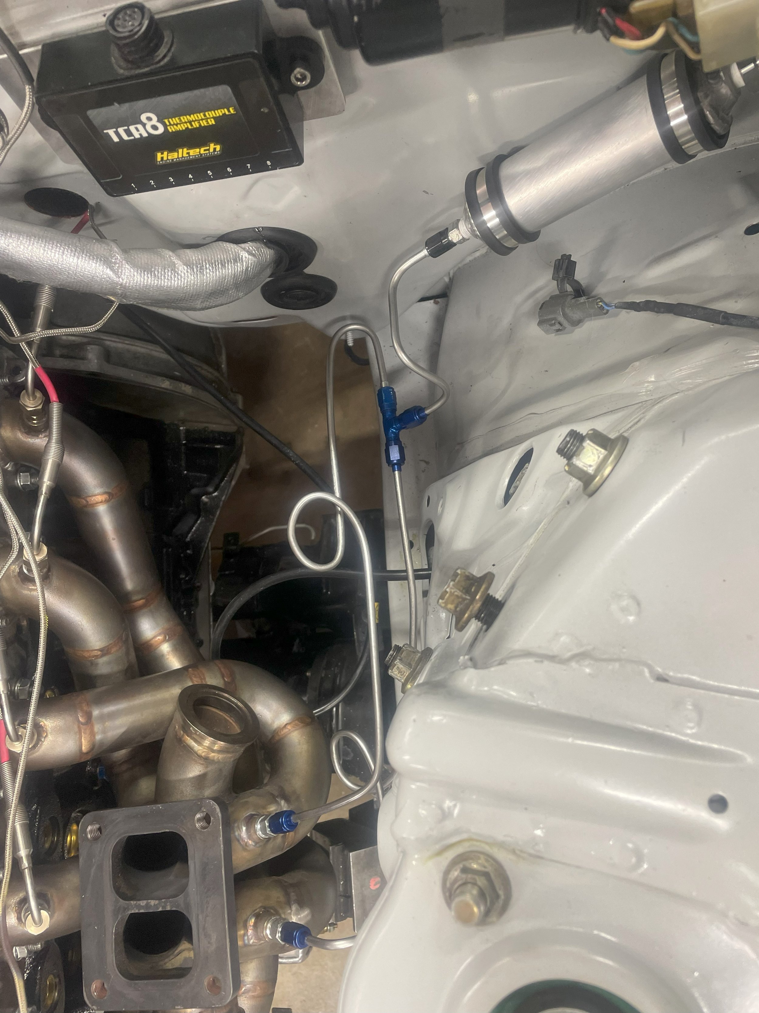
I made a custom made turbo manifold that incorporated individual exhaust gas temperature probes and a exhaust manifold pressure sensor.

In order to keep the turbo in its efficiency range the waste gate placement was critical. This ensures that the turbo responds correctly to closed loop manifold pressure control.

In order to make 1000hp the engine requires a turbo charger. To size the turbo correctly the engine air flow requirements and pressure ratio need to be calculated. Using that information I was able to spec an off the shelf turbo charger that would create a responsive engine. The Turbo would require custom made aluminum charge pipes.
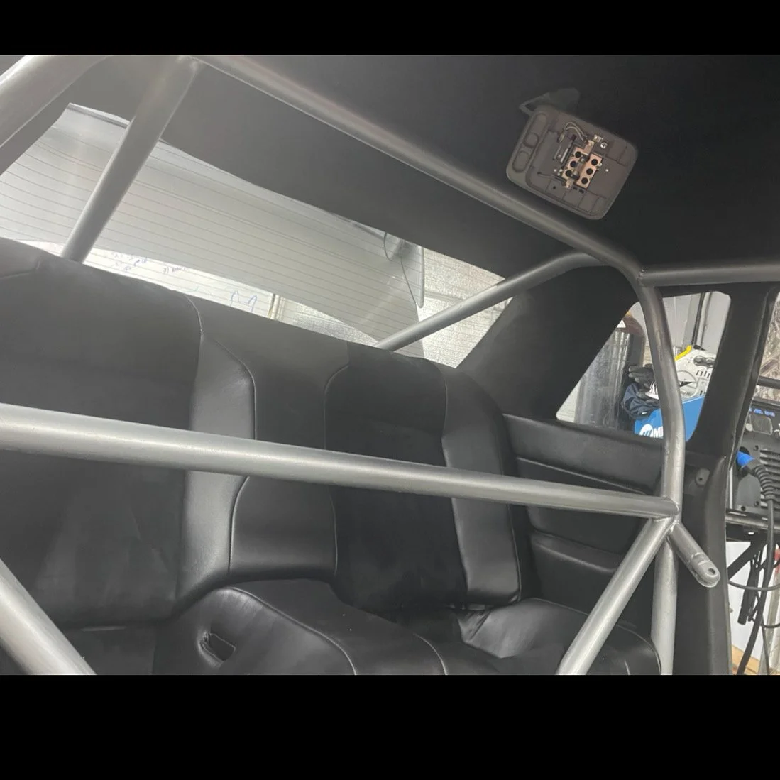
With 1000hp the car requires a roll cage. Using NHRA guide lines I fabricated a roll cage out of 4130 chrommolly. This required the entire roll cage to be TIG welded to prevent altering the material properties.

One of the challenges with the roll cage was to get it to fit properly in the car. Sections of the car were 3D scanned and then the cage was modeled in Fusion 360.

In order to acquire accurate vehicle speed all four wheels were equipped with hall effect sensors and custom tone rings. With this data I was able to create a two stage traction control. When the car experiences wheel slip stage one is to increase pressure to the clutches in the transfer case. If wheel slip continues to increase stage two is a reduction in engine torque.
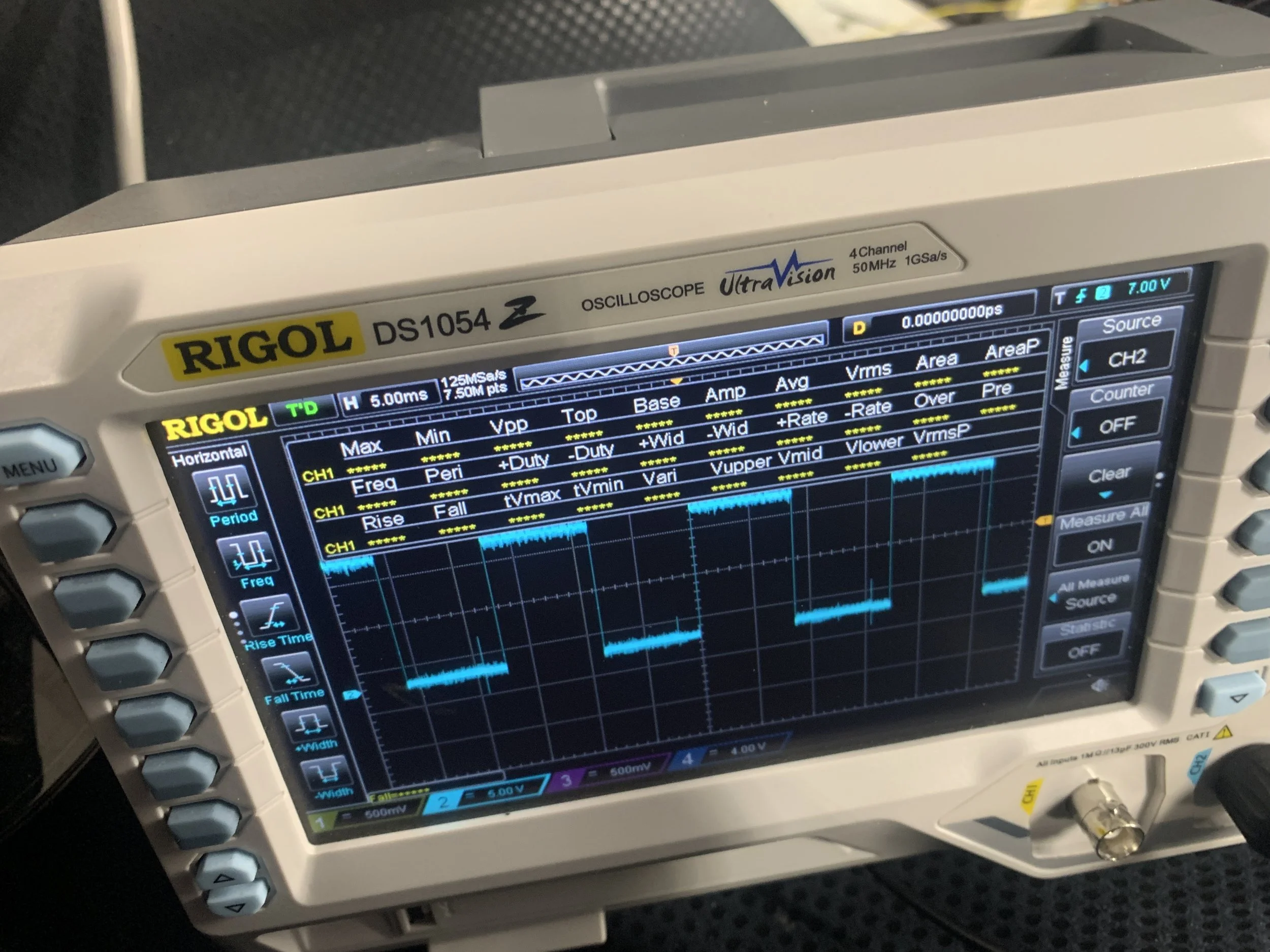
Looking at the signal from a custom designed cam angle sensor. This used off the shelf hall effect sensors and a custom made tone ring.

One of the downsides of using a turbo charger is increased intake charge temperatures that decrease air density. Using CFD I designed an intercooler that minimizes frictional flow losses and allows and maximizes the intercooler efficiencies.